Data
Variables
Variables are primarily used to offer the option of dynamically set values. Mostly used for online documents.
To add variables that are going to be included in texts, you select either Edit/Variables… or use right mouse button click when working in a text. See chapter Generic list dialog
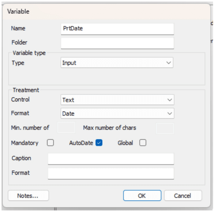
Variable dialog
| Function | Explanation |
|---|---|
| Name | Only optional for new variables. |
| Folder | Set the search path in the variable tree. |
| Variable type/Type | State if the variable is • ContentID (deprecated), • External (deprecated), • Input (user input data), • Link (url link, does not work in conjunction with Font Tracking), • Persistant (deprecated). |
| Variable type/External name | If it is external an external name must be stated (deprecated). |
| Treatment/Control type | If the variable is to be input you must state in what way it will be put in like CheckBox, ComboBox, InsertPoint, Text or Radiobutton. |
| Treatment/Formatting type | State type of data of the variable; can be Date, Decimal, GenitivS, Opening uppercase, Normal, Numeric, Pnr, Postnr. |
| Treatment/Min number of char | State if there are a min number of chars to be put in. |
| Treatment/Max number of char | State if there are a max number of chars to be put in. |
| Treatment/Mandatory | State if the variable is mandatory. |
| Treatment/Global | State if the variable is global in the webeditor. |
| Treatment/Lead Text | State if there is an input lead text for the variable. |
| Treatment/Value(s) | State a list of the values which the variable can take. The values are separated by a comma (,). |
| Treatment/Format | The format instruction for a date. See below for more information. |
If Date formatting has been selected then a slighly different dialog appears, see image below.
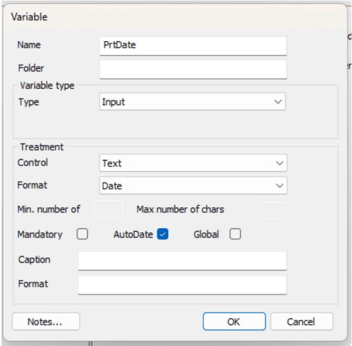
Treatment/Format: Here the date format is defined, using the following characters to define the date format.
| Function | Explanation |
|---|---|
| y | defines year (eg. yyyy = 2015) |
| M | defines month (eg. MM = 01) |
| d | defines day (eg dd = 01) |
A new checkbox named AutoDate is also available. It is used in MetaWrite and WebEditor process applications.
The behaviour for AutoDate differs between MetaWrite and WebEditor.
In MetaWrite the AutoDate is always replaced with today’s date in the Word document when the process has begun.
In WebEditor the AutoDate is not replaced when the AutoDate is in a WriteOff-area, it is just presented as today’s date. In MetaEngine the AutoDate will be replaced with today’s date when generating any final format like AXML, PDF, AFP etc.
Data types
Windows have support to format certain data types according to the locale that is used, like dates, and numbers. Data types make this support available to document developers. To use data types Phrases language has been extended to add a field named “Locale ID”. This Locale ID defines how a data type is to be formatted. For more information see Phrases…
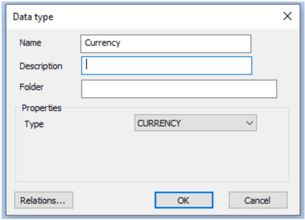
To create a data type the common dialog is used. Press the Add button, and enter a name for the data type and a description, and select the type from the combobox under properties.
The following types are available: TypedScript, SHORTDATE, LONGDATE, CURRENCY, NUMBER, and CUSTNUMBER.
TypedScript is used to create a formatting using a Script. To help creating to handle data type a new method exist in helping writing a TypedScript. The method name is “GetTypedValue”. See “GetTypedValue” for more information.
A defined data type is then available in Test data when editing a text. For more information see Texts…
The data value in that is to be processed by a defined data type must have a defined format for it to work. Dates must be initially in yyyy-MM-dd (ISO) format for it to work. Numbers/Currencies must only contain numbers and any decimal character must be a period (.). If input data cannot conform to these constraints then a TypedScript can be used to prepare the data before it is used by any of the standard data types (e.g. SHORTDATE, LONGDATE and others) in a TypedScript.
Starting with Interact version 11.5 it is possible to override the inherent behavior from the OS when formatting CURRENCY, SHORTDATE and LONGDATE by specifying formatting rules for different locales in the Language dialog. Please, note that while the language settings is keyed by the Code column, it’s not possible to have the same Locale ID for different entries of the key Code, for the overrides to work properly. See chapter Phrases for more information on the Language dialog.
Table format
If you want to structure the information in your document, you have to create a table format first.
To manage or add Table formats you select Edit/Table Format… See chapter Generic list dialog.
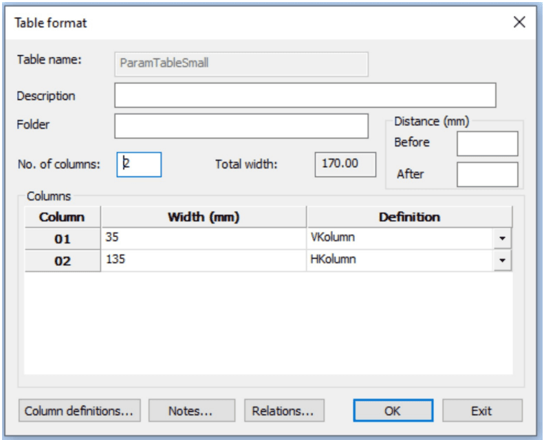
Table format dialog
| Function | Explanation |
|---|---|
| Table name | Only optional for new table format. |
| Number of columns | State number of columns in the table. |
| Total width | Automatically calculated total width of all columns in mm. |
| Space (in mm)/Before | State space in mm before each row of the table. |
| Space (in mm)/After | State space in mm after each row of the table. |
| Columns/Width in mm | State width of the column in mm. |
| Columns/Definition | State if the columns are to be connected to a definition. |
Press Column definitions… to change and create new column definitions. See chapter 18.1 Column definitions.
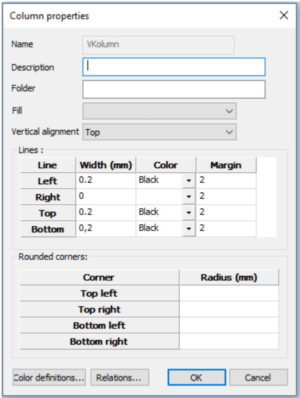
Column definitions
If you have frequent tables of the same style in your document, it is a good idea to create column definitions. To add or change column definitions you can select Edit/Column definitions… . See chapter Generic list dialog.
| Function | Explanation |
|---|---|
| Name | Only optional for a new column definition. |
| Description | A descriptive text of the column definition. |
| Fill | Select the color filling, if any, for the columns from the drop-down list. |
| Vertical alignment | By using vertical distance you can change the vertical alignment of text in a column, top, center, or bottom. |
| Line/Width | State width (in mm) for the four surrounding lines of the column. |
| Line/Color | State color for the four surrounding lines of the column. |
| Line/Margin | You can set one or more margins in the table cell. |
| Rounded corners/Radius | State radius of rounded corners (in mm) if any, for the four corners of the column. Note: If a column is defined with a fill color, the left and right radii should be the same for the fill color to align properly. Having different radii on the top and bottom is acceptable, as is having one corner with a radius and another without. |
| Color definitions | See chapter Color definitions. |
Inline Table format
To be used to do tables without table- nor column definitions.
This format is usefull when dealing with seldom used tables and column definitions, where using reusable objects is just a hazzle that slows down the workflow
Inline Table workflow
Chose “Inline table…” from the “Insert” menu of the text editor’s context menu.
This will place an empty Inline Table in the text.
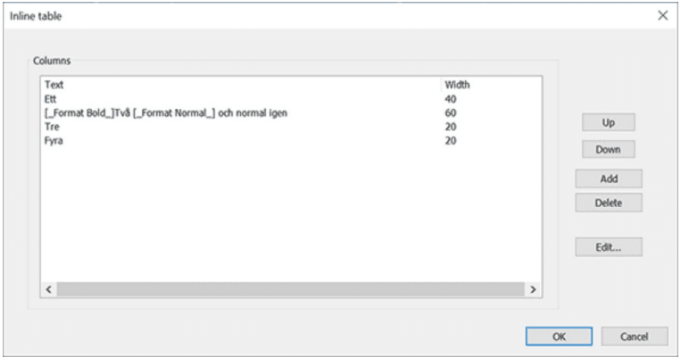
Double-clicking the InlineTable header in the text will open a dialog to define the table:

Click “Add” to insert a column:
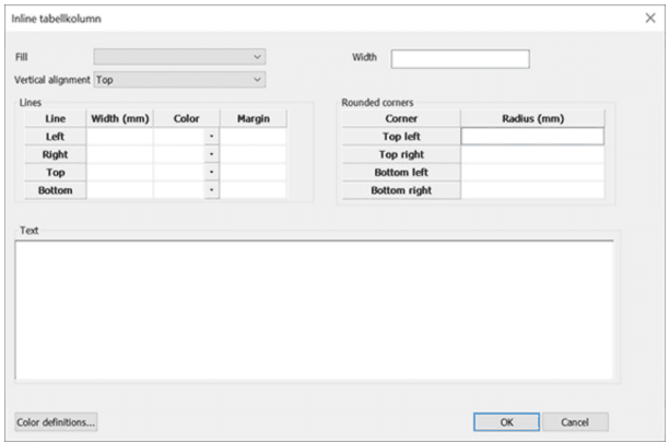
From here you can set the properties of the Column without having to refer to a predefined Column definition.
The dialog also expects a column width that cannot be empty.
The text field resembles what you get in a Text box, but with context menu items enabled/disabled for use in this context.
You can add as may columns as you want for a table block. Columns can be reordered and deleted from the Inline Table dialog as well.
Editing can be done with the “Edit…” button or by double-clicking a row.
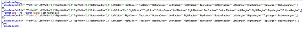
Working with dialogs creates the tags in the text editor. You can access the table dialog at any time by doubleclicking the InlineTableBegin start tag and access any column’s dialog directly by double-clicking the “InlineTableCell” tag inside the InlineTable.
Forms, “static forms”
A form is - from a formatting point of view - a fragment which is static in height and width. A form can be located absolutely or dynamically on the page. A form is created either of two ways. The first method is to right click on Form in the resources view and then select New (or Copy). The other method is to import a form from a PDF.
- The font should exist in the Metaforce font directory
- The font should exist in the Windows font directory during the import as well, to get the text boxes properly aligned and with the right sizes.
If a PDF form contains fields, the names of the fields are saved as an Import id. If the PDF form is imported again, the import id is used as an identity, which is matched against the PDF field name in order to keep the name you have given to the variable, which inputs the field (only the graphic properties like font and location are updated).
The advantage of forms is, that in AFP and in PostScript they are regarded as static objects put at the top of the print file (so called inline resources). The AFP/PostScript file is smaller as well as is the document generation speeded up since the drawing operations only have to be executed once.
Importing PDF directly in Metatool
New from version 11.3 is the abilty to import a PDF file directly from MetaTool without using Metaforce PDF2XML. See document Metaforce PDF2XML for more information on using the latter one.
Importing PDFs is done in the same way as importing XML files. Both can reside in the same folder. To achieve the best possible result when importing a form directly from a PDF without using the plugin, please keep in mind that using the correct fonts is of paramount importance:
Introduced in version 11.7 is the capability to incorporate images and vector objects during the direct PDF import process. This feature significantly streamlines the import procedure. However, it is important to note that the PDF format is both aged and exceedingly intricate, encompassing numerous features incorporated over the years. Consequently, deciphering and accurately interpreting the PDF format can be challenging, leading to potential parsing mistakes. We anticipate the existence of imperfections and would greatly appreciate receiving PDF files that are not handled optimally by the import function.
Some use cases, however are not aligned with the inner workings of the document engine and thus are not likely to be fixed in the near feature.
They include:
- Transparent vector graphics (though completely transparent background will work).
- Clipping regions. Applies to both bitmaps and vectors.
- Bitmaps or vectors partially outside the borders of the form.
- Complex layers. All vectors will always have z-order “1”, that is they will be placed in the background. This can be changed in the Form’s Object List, but will affect all vectors as they are placed as one unit.
Please, also note:
- There is no way of seperating for instance a vector logo, from other vectors on the form. If you opt for importing vectors, all vectors will reside in a background vector object, with the size of the form. See later notes on the implications when setting CMYK-colors.
- Forms and vectors are made unique by hash and size (which will be reflected in the name of the resource). This means that a bitmap or vector can be reused on other pages of the import or in another import in the same MetaLogic for that matter. See later notes on the implications when setting CMYK-colors.
- Please, note that the name of the imported PDF is used as folder name, the first time a resource is encountered. If a similiar resource is found in a later import the resource will be reused but folder name will still look like it’s only used in the former import. If so, feel free to change folder name to something more adequate, for the sake of clarity.
- Some bitmaps may be constructed by combining several tiny bitmaps. This will not look good on the form. The only solution is to remove them and import a corresponding bitmap separately.
- All bitmaps, as for now, are imported with resolution 300 dpi to make the import more straight forward.
When including images and vector objects the import process will generate image and vector resources and naming them based on the MD5-value and byte-length of the resource. Remember to map RGB-colors to CMYK-colors for all vector objects generated if you will do AFP-print. This must be done every time a new PDF is imported.
An advisable approach is to establish a “Jump Solution project,” in which you import PDF forms along with their associated resources, meticulously examining the outcomes. Upon achieving contentment with the results, you can then transfer the form resources to the destination project. By following this method, you effectively segregate unused image and vector objects within the “Jump Solution project”, rather than within the intended destination project.
Import form
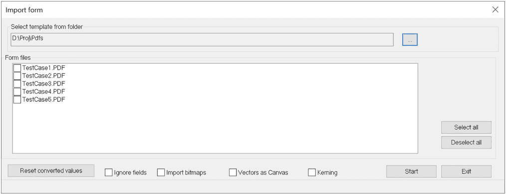
To import a form select Home/Import form…
| Function | Explanation |
|---|---|
| Select template from folder | Select […]-button to select a directory for forms. |
| Form files | List available forms in a directory. |
| Reset conversion values | Clears all saved conversion values for fonts. |
| Ignore fields | Ignore input fields in the PDF. |
| Import bitmaps | Imports bitmaps as image objects. |
| Vectors as Canvas | Imports vectors as canvas objects. |
| Kerning | Adds kerning info to the import. |
| Start | Start import of selected form. |
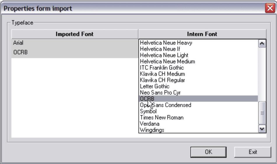
Properties form import you select the Metaforce fonts equivalent to the ones in the form.
Read more in the Metaforce Fonts document.
Work with the forms editor
The form is shown in the forms editor:

| Function | Explanation |
|---|---|
| ID | The identity of the form. Can not be changed in Change under resources. |
| Description | A text describing the form. |
| Folder | Set the folder name in the forms tree. |
| Imported file | Show the name and the directory of the imported file. |
| Properties/Width | Show the width of the form. |
| Properties/Height | Show the height of the form. |
| Properties/Distance before | The distance to the form. |
| Properties/Change | Change the properties of the form. |
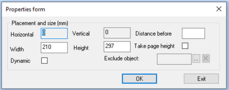
| Change | Properties form |
|---|---|
| Placement and size in mm/Horizontal & Vertical | Can not be changed. |
| Placement and size in mm/Distance before | State space before form. |
| Placement and size in mm/Take page height | State if the form is to take page height, see below for more information. |
| Placement and size in mm/Width | The width of the form in mm. |
| Placement and size in mm/Height | The height of the form in mm. |
| Dynamic | If the form is to be dynamic. |
Dynamic properties for a form imply that the form is shrunk vertically, which means that all white space before and after disappears. This is making it possible to create smaller form fragments, which dynamically can follow the document (float over the pages). If Take page height is selected, the height is added, when the pages are composed. Each form fragment is kept together on one page.
![]() Standard Tools icons: Cut/Copy/Paste and Print a form.
Standard Tools icons: Cut/Copy/Paste and Print a form.
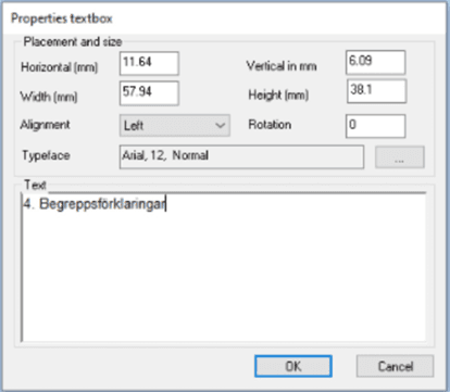
 Insert textbox: Mark in the form where to put a textbox, and then double click on the marked field to get the dialog for textbox, see below.
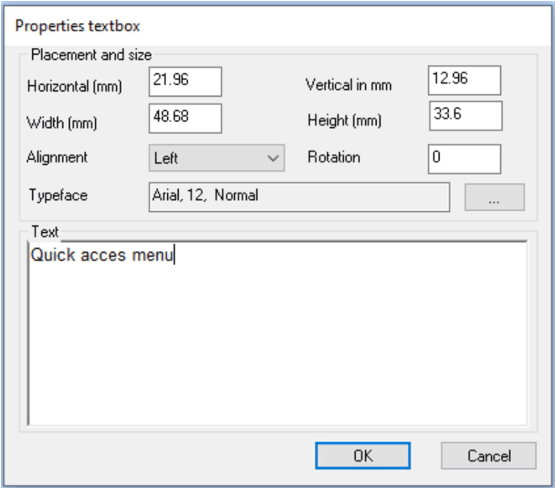
| Function | Explanation |
|---|---|
| Placement and size/Horizontal in mm | The position of the field relative to the left start position of the form. |
| Placement and size/Vertical in mm | The position of the field relative to the top start position of the form. |
| Placement and size/Width in mm | State width of the field. |
| Placement and size/Height in mm | State height of the field. |
| Placement and size/Alignment | State alignment of the field (Left/Centre/Right). |
| Rotation | State in what angle the text is to be rotated. The following standard degrees are supported by all output formats 0°, 90°, 180° and 270°. For PDF, PS, and PPML the degrees can be between 0-360° degrees. If a degree is stated that is outside the standard format and the output format do not support the stated degree, it is rounded to the nearest valid standard degree (0°, 90°, 180° and 270°). |
| Font | State font of the field, click […] button to change. |
| Text | Text content for textbox. |
If you have imported a form where the XML file is made from a PDF file which include text indicies, then you will see this new button show.
If you want to make changes in the text, you select Remove text indicies.
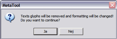
Indicies will be deleted in the actual text. The button Remove text indicies will only show up in a form with static texts.
| Function | Explanation |
|---|---|
| Mark in the form where to put a rectangle, then double click on the marked field to get the dialog for rectangle. See chapter Texts - Rectangle… for more info. | |
| Mark in the form where to put a line, and then double click on the marked field to get the dialog for line. See subchapter Texts - Line… for more info. | |
| Mark in the form where to put an image line, and then double click on the marked field to get the dialog for image. See subchapter Image… for more info. | |
 | The picture means an empty image in the image editor. Double click on the area to get the dialog for image properties and select required image. |
| Mark in the form where to put a field, and then double click on the marked field to get the dialog for field. See below. |
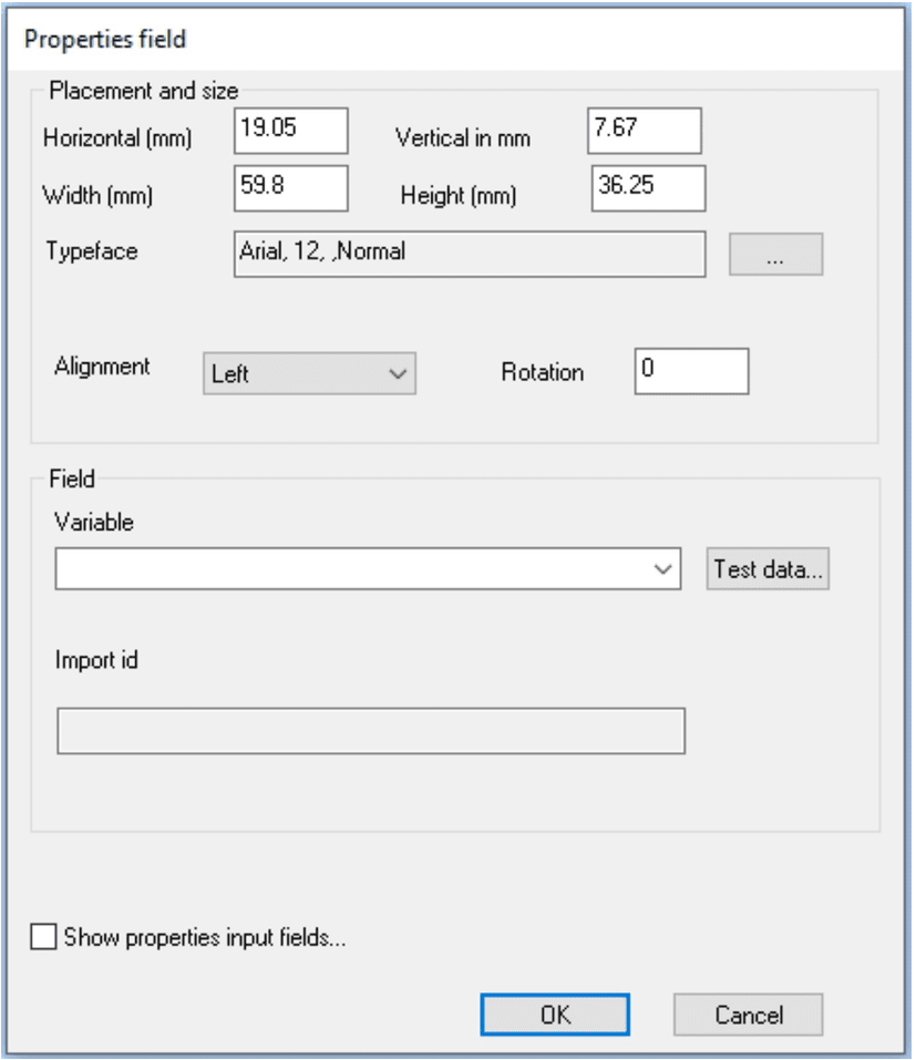
| Function | Explanation |
|---|---|
| Placement and size/Horizontal in mm | The position of the field relative to the left start position of the form. |
| Placement and size/Vertical in mm | The position of the field relative to the top start position of the form. |
| Placement and size/Alignment | State alignment of the field (Left/Centre/Right). |
| Placement and size/Width in mm | State width of the field. |
| Placement and size/Height in mm | State height of the field. |
| Placement and size/Rotation | State in what angle the field is to be rotated. The following standard degrees are supported by all output formats 0°, 90°, 180°and 270°. For PDF, PS, and PPML the degrees can be between 0-360°degrees. If a degree is stated that is outside the standard format and the output format do not support the stated degree, it is rounded to the nearest valid standard degree (0°, 90°, 180°and 270°). |
| Placement and size/Typeface | State font of the field, click […] button to change. |
| Field/Variable | State a variable for the field. |
| Field/Import id | ID for the field is created when imported. Used to store earlier field preferences when importing the same form again. |
| Show properties input fields | See manual MetaWrite manual. |
![]() Lists all objects in form, the selected item is marked in the form.
Lists all objects in form, the selected item is marked in the form.
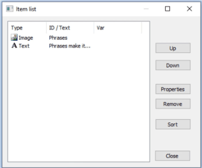
| Function | Explanation |
|---|---|
| Up/Down | Changes the order in the list Up or Down. |
| Properties | Displays the type’s properties. |
| Remove | Remove the type from the list, can not be undone. |
| Function | Explanation |
|---|---|
| Adjust the positioning of all marked objects to the position of the first marked object. | |
| Adjust the size of all marked objects to the size of the first marked object. | |
| Show a grid over the form. | |
| Change the fonts in the form. See below for more information. |
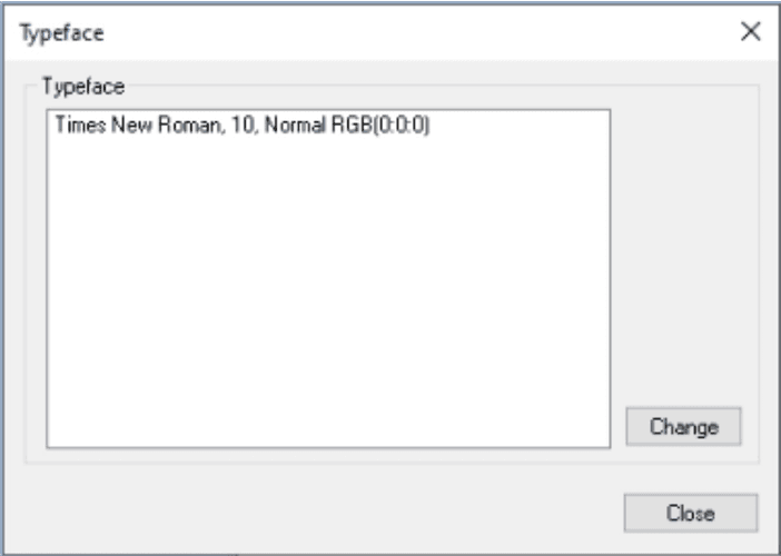
Typeface: The list of fonts used by the form. The program scans the form and lists all the fonts contained in the form. If you change a font here, all the instances where the font is used in the form are changed.
![]() Change colors: Change the colors in the form.
Change colors: Change the colors in the form.
Colors:
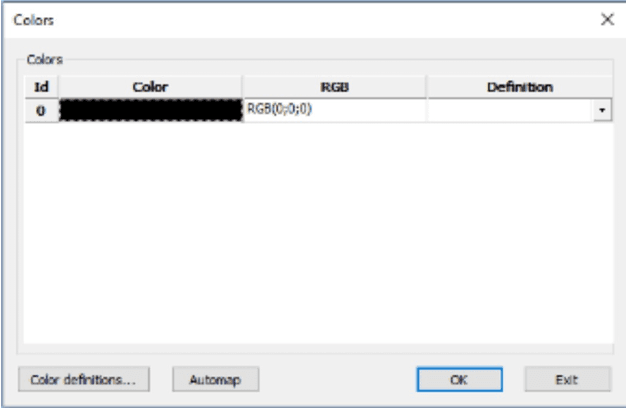
Color definitions… Set the precise color code in RGB and CMYK.
![]() Preferences editor: State which preferences to be used when editing a form. See below for more information.
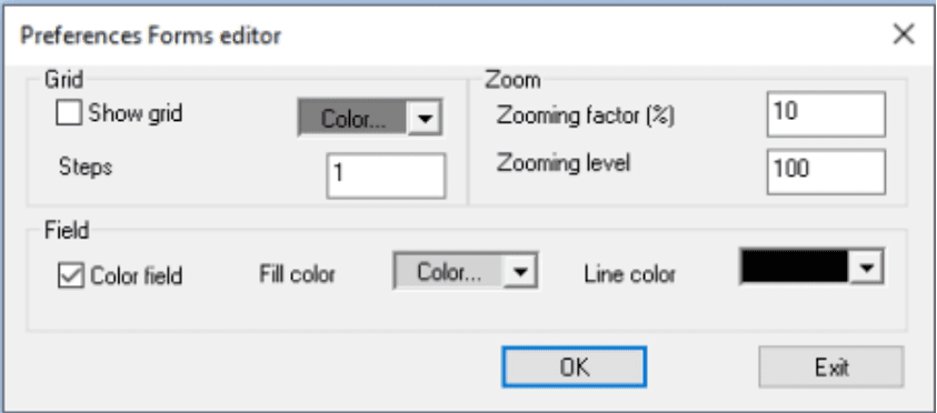
Preferences editor: State which preferences to be used when editing a form. See below for more information.
| Function | Explanation |
|---|---|
| Grid/Show grid | State if grid is to be shown. |
| Grid/Color… | Color of grid. |
| Grid/Step in mm | The size of the squares in the grid. |
| Zoom/Zooming factor (in %) | Percentage… Zoom increase/decrease. |
| Zoom/Zooming level | Default zoom level. |
| Field/Color field | Color a field for easier identification in a form. |
| Field/Fill color | Background color of a field. |
| Field/Line color | Line color. |
Context menu
Group/Ungroup: By marking several objects (press Crtl button and mark with the mouse) you can logically group the objects in a unity which is easily moved round the form. See below for an example.
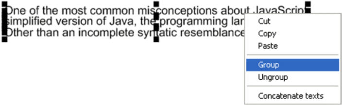
Concatenate text: When importing forms from a PDF each text line comes as a separate text window. If the text lines have the same font, you can mark several text lines (see above), right click outside the text lines and combine all lines in one big text window by marking Concatenate text. See below for examples.
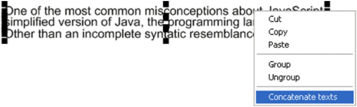
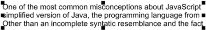
Here are the text lines as one large text window after the concatenation operation.
Image…
To add images that are going to be included in the documents, you select either Edit/Images… or use right mouse button click when working in a text. See chapter Generic list dialog for the first approach. When inserting an image into a text you’re not directed to the Generic list dialog, but to the Properties Image dialog. This dialog will give you the chance to decorate the image tag with metadata describing how the image will be displayed in the context of the text.
Properties Image dialog
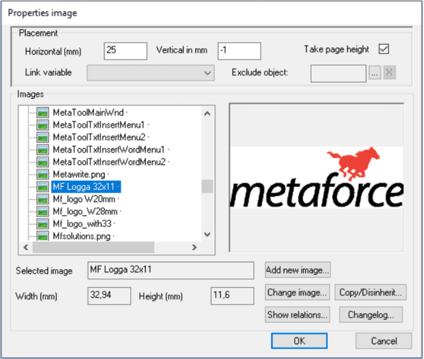
Placement:
| Function | Explanation |
|---|---|
| Horizontal in mm | The X-value location of the image in mm. |
| Vertical in mm | The Y-value location of the image in mm. |
| Take page height | State if the image is to take page height. |
| Exclude object | Opens dialog for suppressing the selected image when using certain print configurations. |
Images:
| Function | Explanation |
|---|---|
| Selected image | Selected image, not to be changed. |
| Width in mm | The width of the image in mm, not to be changed. |
| Height in mm | The height of the image in mm, not to be changed. |
| Add new image… | Select an image from the directory structure. |
| Change image… | Change a selected image. |
| Show relations… | Is used to find out where in a document a text object occurs. See chapter 25 Show relations. |
| Copy/ref | Is available when connected to a Solution. See chapter Solution. |
Select Insert => Image..
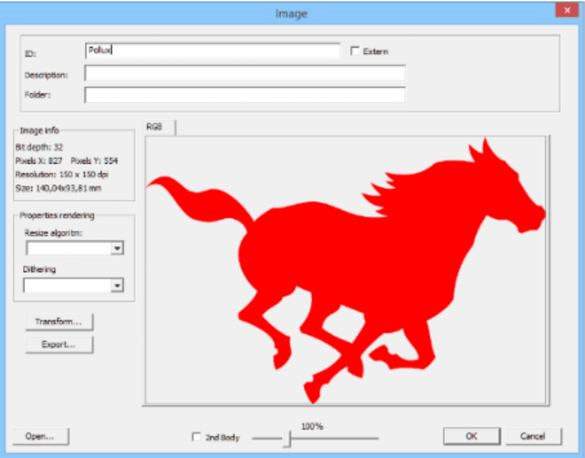
Add/Change Image dialog
| Function | Explanation |
|---|---|
| ID | The name of the image, must be unique. |
| Description | The description of the image. |
| Folder | Used to group images. |
| Image info | Describes image size and color depth. |
| Properties rendering | Describes algorithms to be used when resolution and/or bit depth in print configuration file differ from the image. |
| Open… | Opens an image from disc. Possible extensions are .tif, .jpg, .cmp and .png. |
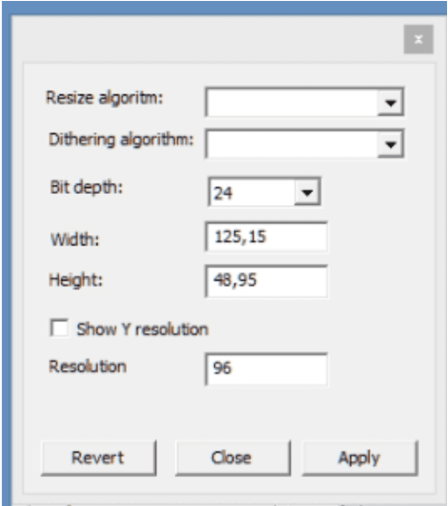
| Transform… | Opens a dialog for changing size and/or bit depth of the selected image. |
| Export… | Exports an image to disc as .jpg, .cmp, .tif or .png format. |
| Extern | Shows if the image is saved externally, outside MetaTool. |
| 2nd Body | If the image needs two color definitions. Both RGB and CMYK. |
Image properties includes several possibilities for you to print your image just the way it is expected. Functions like Properties Rendering, two different kinds of algorithms used to change size and bit depth of an image makes this possible. If you do not know which algorithm to use, try them out one by one until you get the results you want. A test print out shows the image in PDF format.
If the size of your image does not match the properties of a certain print configuration, then you can modulate its size by transforming it.
Note.If your image have a CMYK body it can lose its proper color values when transforming it by changing size etc. Therefore it’s better to transform the CMYK-image before importing it to the tool.
Transform…
Here you have the option to add an algorithm again, but also the possibility to change size and bit depth of your image.
Additional image information
**Output channels configuration:**Images when they are printed are affected by the Output channels configuration definition file, PrtConfig.xml in “Prt\Conf” directory, see chapter Output Channel Configuration for more information. Things that can affect the image is for example the XResolution/YResolution settings in the Output channel file (PrtConfig.xml).
Extern checkbox: An image can be defined as extern by checking the checkbox, this may affect the image, i.e. if it contains a color profile then the color profile will be removed by MetaTool. When OK button is pressed then the image is processed by MetaTool and created under “MetaDir\Image” directory. The processing will not affect the image resolution except for already stated remove any color profile.
Exclude object: Can be used to exclude/include images for specified Output channel definitions but otherwise do not affect images, but it can be the reason images are not printed, see chapter Exclude object for more information.
Vector objects…
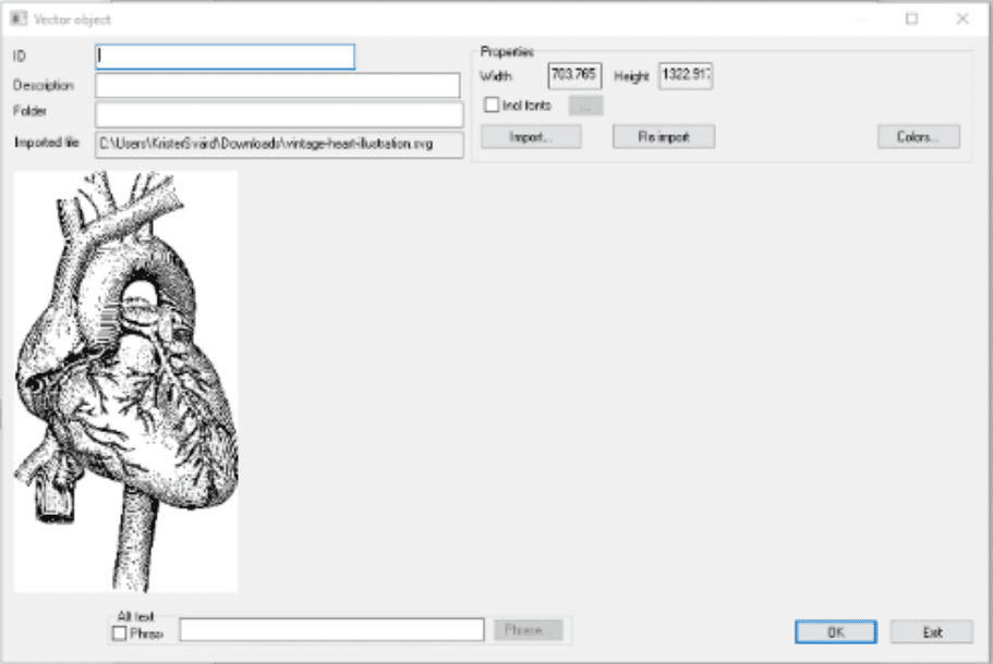
To add vector objects that are going to be included in the documents, you select either Edit/Vector objects… or use right mouse button click when working in a text. See chapter Generic list dialog for the first approach. When inserting a vector object into a text you’re not directed to the Generic list dialog but to the *Properties Vector objects dialog. This dialog will give you the chance to decorate the object tag with metadata describing how the vector object will be displayed in the context of the text.
Note: It is not possible to use vector objects in process step forms or in editable forms presented in MetaWrite documents.
Vector graphics
Buttons and Checkboxes:
| Function | Explanation |
|---|---|
| Import… | Import a XAML or SVG into the MFL |
| Incl fonts | Include fonts when importing an SVG object. This is relevant when a SVG object contains text (glyphs) that also should be included when doing the import (generating the vector items of the text items). |
| … | When including fonts the import program will as default use “C:\Windows\Fonts” as its source. One can include yet another font directory for inclusion as well. This choice will be saved until changed or cleared with the X-Button. |
| Colors… | Change of colors for the object |
| Re import | Re import the vector object (useful when a vector includes glyphs) |
| Relations… | List the relations for the vector object. |
Import of vector graphics as SVG.
Instead of going the “XAML-way” one can use the SVG import instead :)
Limitations
Vector objects containing gradients, transparency or clipping regions will loose these attributes in the import. The latter ones will frequently occur without making any obvious diffrence to the result and are because of this ommited from the warnings you get from other objects that are skipped. They may however make a difference, but this should be obvious when studying the preview.
Getting a warning like this when importing an SVG means the vector includes fonts that could be included like vectors:

To get the fonts as vectors, check “Incl fonts” and press button “Re import”. To match the appearance of the original, the font must exist in Windows/Fonts or in the extra font directory you have included. Please note, that importing a lot of text this way, may result in quite large vectors in the Logic File! Text in a logo should be fine, but most certainly not a whole page of text.
Import of vector graphics as XAML.
XAML should be “Silverlight compatible” and have a Canvas element as root node. Namespace declaration should be http://schemas.microsoft.com/winfx/2006/xaml/presentation and the root Canvas object must have a size and a width.
Example:
<Canvas xmlns="http://schemas.microsoft.com/winfx/2006/xaml/presentation" Name="svg4136" Width="796.59497"
Height="796.59497">
Tested and recommended process to import vector graphics (in XAML format)
The Inkscape application (freeware) is a tried vector graphics tool to pre-process vector graphic files into the XAML-format manageable by Metatool.
- Open up the SVG vector graphics file in the Inkscape application
- Save the file as an “Enhanced Metafile” format with all options checked. This will convert complex vector objects into simpler vector paths. Close the Inkscape application.
- Open up the “Enhanced Metafile” file in the Inkscape application and save the file as a “Microsoft XAML” format with the “Silverlight compatible XAML” option selected.
- Import the produced XAML file as a vector object into Metatool.
Properties Vector object dialog
Select an existing object from a text item and set the specific properties for it.
| Function | Explanation |
|---|---|
| Vector | Select a vector object from list. |
| Horizontal in mm | The X-value location of the object in mm. |
| Vertical in mm | The Y-value location of the object in mm. |
| Width in mm | The width of the object in mm, not to be changed. |
| Height in mm | The height of the object in mm, not to be changed. |
| Take page height | State if the object is to take page height. |
| Static… | Checkbox to select if the Vector object should be absolute positioned or dynamic in the document body flow. |
Colors for a vector object
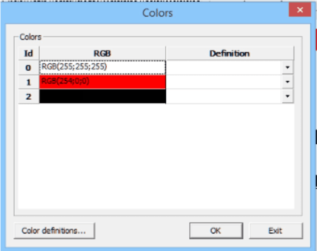
One advantage of using vector graphics instead of bitmaps is the precise handling of colors for any part of the image. When printing photos you’re stuck with bitmaps. More often than not, these bitmaps originates from the RGB color space and need to be converted to CMYK before print.
This is usually not a problem as the eye will tolerate the shortcomings of this process when dealing with a photo with a lot of different nuances of color. When it comes to more stylized graphics like logotypes, the situation tends to be different though. It’s much easier for the eye (or really the brain…) to note any deviation from the expected when dealing with these much more simple objects. This is where vectors graphics really shine. You can define the precise color value for every color of any part of the graphics and in MetaTool, you can do so not just for CMYK when going for high quality print, but for RGB as well when the graphics are bound for digital output.
As color handling is so essential for the benefits of vector graphics, it’s not just possible to tweak the colors, but you have to do it and you have to use predefined color definitions when doing so!
See chapter Color definitions
Resizing a vector object
Vector graphics are resizable by design!
Bitmaps consist of pixels. To shrink an image the computer has to remove pixels. To blow up an image, pixels have to be added. Either way the quality suffers more or less, even though algorithms are used to reduce the impact.
Vector graphics, on the other hand contains the recipe of an image, for the computer to use when constructing pixels for the printer or the screen. This means that the same image can be used with different sizes without any quality degradation. (Not absolutely true as the resolution of the output media naturally sets the limits, you can never do better than that…)
This makes it much easier when importing graphics. You don’t have to bother too much of the size of the original and you can even use the same imported graphics with different sizes on different circumstances.
AFP and Vector Graphics
AFP is still the most common format for high volume print. Being designed from the very beginning for black and white printing with bitmapped fonts and simple graphics the standard as well the capabilities of the printers have developed over the years. Full color printing was for long regarded as exotic and expensive but is now a real option.
Support for Vector Graphics is quite extensive by the AFP standard but the printers and rippers however, are still slipping behind.
To handle the imperfection of printing hardware and software it’s possible to tell MetaEngine to rip the vector graphics to bitmaps at runtime. In this way you still get the benefits of color handling and loss free scaling while using legacy AFP equipment. It should be noted however that very large vector objects will grow memory wise to the same size as if it was a bitmap from the very beginning.
It’s also possible to convert Bezier curves to polylines at runtime, which may be consumable for more printers than Bezier curves even though some quality degradation could be expected. See chapter Output Channel Configuration.
Limitations for vector graphics
MetaTool will not be able to import all kinds of objects, possible in a XAML document. Texts and bitmaps, as well as other complex types like gradients will be skipped. MetaTool will warn when omitting any object and the residual graphics will still be possible to use if desired.
One way to keep texts in graphics is to convert glyphs to graphic paths in for example Illustrator before export. The disadvantage of doing so is that one loses any possibility to manipulate this text afterwards. On the other hand, the text could be arbitrary rotated, which otherwise would be impossible in AFP output. It will even be possible to use artwork with fonts not installed on the server!
The imported XAML cannot contain references to external code like event handlers or owner defined graphic objects.
It’s should be noted that it’s possible to import vector graphics, not to edit them (even though the colors are freely customizable). This pretty much confers to our philosophy concerning bitmaps: there’re better tools out there for doing so!
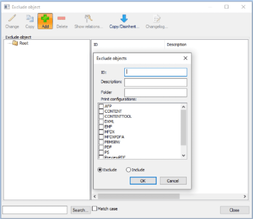
Exclude Object
The Exclude Object dialog holds a list of exception objects containing names of print configurations that shouldn’t be rendered when the exception object is tied to an entry of the image, for instance.
To manage Exclude Objects, you select Edit/Exclude Object. See chapter Generic list dialog.
By using exception objects, listed in the Exclude Object dialog, you can decide which images to print and how, or not print at all. You may have a document with a few inserted images of different sizes, color, black and white and with different resolutions. Lets say the document you are about to print first shall for the first set of prints not print color images. In the Exclude Object dialog, you therefore choose the exception objects that excludes printing anything but black and white images.
Maybe the third time it is time to print the accurate document, all images included. Select the exception object that excludes no Exclude Objects.
Exclude Object dialog
Color definitions
It is possible to declare color profiles for both RGB and CMYK.
If you use colors frequently in your document, it is a good idea to create color definitions.
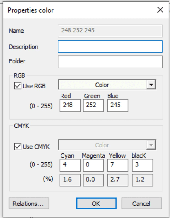
Properties color dialog:
| Function | Explanation |
|---|---|
| Name | Only optional for a new color definition. |
| Description | A descriptive text of the color. |
| RGB/Use RGB Checkbox | Check for updating of RGB color code. |
| RGB/Color dropdown list | Select predefined color from color scheme. |
| RGB/Red | Value 0 - 255. |
| RGB/Green | Value 0 - 255. |
| RGB/Blue | Value 0 - 255. |
| CMYK/Use CMYK Checkbox | Check for updating of CMYK color code. |
| CMYK/Color dropdown list | Select a predefined color from color scheme. |
| CMYK/Cyan | Value 0 - 255. Value is presented in percent below. |
| CMYK/Magenta | Value 0 - 255. Value is presented in percent below. |
| CMYK/Yellow | Value 0 - 255. Value is presented in percent below. |
| CMYK/Black | Value 0 - 255. Value is presented in percent below. |
Note! For CMYK values you are recommended to use the 0 - 255 scale and not percentage (as in Photoshop for example), as this is a more exact color definition. The CMYK color you will see on screen in the tool can look different than you expect. Do not worry though, the color will be alright when printed.
Pure CMYK Workflow
The preferred color space for most print shops is still CMYK. This is quite natural as CMYK is a subtractive color model specially designed for reproducing reflected light, which really is what you see when looking at paint on paper. RGB, being an additive color space, on the other hand is optimized for computer screens and is what is most often used in cameras, on the web etcetera. It’s quite possible, even in Metaforce, to convert RGB images to CMYK ditto, using ICC profiles, which are basically mapping tables from one value to another.
The problem however, is that an RGB color space (yes, there are several…), consists of different colors than a CMYK one. The ICC profile just finds the closest match. For most colors, this is fair enough or even spot on, but sometimes it’s just way off. This is especially bothersome when displaying well known colors like the ones building up a logotype where the right color for many people is easy recognizable by mind and very often a part of trademark owner’s DNA.
To be able to keep the fidelity of the original colors, it’s desirable to avoid ICC translations from one color space to another as information will inevitably get lost. Because of this one can store images as CMYK as a second image body in MetaTool, when there is a chance that the image will be used for AFP print. The RGB body needed for PDF, HTML and other screen formats is always stored.
When printing photos, there’s a fair chance, that RGB->CMYK through ICC profiles, will be sufficient. The human eye seems to be less picky when dealing with photos than spot colors!
ICC Profiles
Metaforce supports two kinds of ICC profiles:
- Input Profiles
Input profiles are used to describe the intent of the producer of the image. As the number of possible colors a pixel can represent are limited, you have to choose what part of the visible spectra you’re using when you’re describing the world. To do so, predefined color spaces, like “sRGB”, “Adobe RGB” etc., are used, each representing their own part of the world.
Of course they overlap, but some could have more colors suitable for representing human skin for example and because of this sacrificing other colors.
If an image has a built in ICC input color profile, this one will be used. If the image contains metadata about an external input ICC profile of type sRGB or AdobeRGB, this will be used. Otherwise, if doing a CMYK separation, the input profile specified on the AFP profile will be used.
- Output Profiles
Output profiles are used for transforming an image to its output format, typically when doing a CMYK separation that is transforming an RGB image to a CMYK image.
When doing so, the input profile (what’s the intent) is used together with the output profile (what CMYK value corresponds to a given RGB value).
The output profile is specified on the AFP profile in the print configuration.
If no profile is specified, the CMYK values are computed mathematically. Mathematics can be beautiful but not on this occasion…
This probably should be avoided, if not working with a print shop with very good understanding of colors.
Recommendations regarding color management in Metatool when doing CMYK (AFP)
From a color perspective and CMYK there are two types of objects that need attention:
- images like photos and
- vector based object.
In the regards of vector based objects we include Vector objects, Texts, Lines and Rectangles.
Working with logotypes and other objects that are important to have a good color match, import them as Vector objects (and use Color definitions). Do not import them as images as you most likely will be unsatisfied with the result.
Recommendations regarding Images
Used the built in RGB to CMYK conversion in Interact using ICC profiles. Ask your printshop what ICC profile they have calibrated their printers with and use this ICC profile when generating the AFP files.
If you’re not satisfied with the result using the built in RGB to CMYK conversion you can always include a second image body where you do the RGB to CMYK conversion in another tool than Interact.
Recommendations regarding Vector based objects
Use Color definitions and define CMYK values for all important colors. Work closely with the printshop and do test prints to see the actual result. Colors without Color definitions will be converted to CMYK using the built in color transformation in Interact and the result may vary.
AFP color channels predefined in Interact
There are 4 AFP channels with color profile predefined in Interact with different characteristics:
- AFP
- AFP_RASTERIZE_VECTORS
- AFP_47_RASTERIZE_VECTORS
- AFP_29_RASTERIZE_VECTORS
| AFP channel | Explanation |
|---|---|
| AFP | RGB to CMYK conversion is done using the CoatedFOGRA39 profile. Vector objects are generated as GOCA (graph objects) in AFP. |
| AFP_RASTERIZE_VECTORS | RGB to CMYK conversion is done using the CoatedFOGRA39 profile. Vector objects are generated as IOCA (image object) in AFP. The reason for generating IOCA instead of GOCA is the varied support for GOCA in AFP printers. |
| AFP_47_RASTERIZE_VECTORS | RGB to CMYK conversion is done using the PSO_Uncoated_ISO12647_eci profile. Vector objects are generated as IOCA objects in AFP. |
| AFP_29_RASTERIZE_VECTORS | RGB to CMYK conversion is done using the UncoatedFOGRA29 profile. Vector objects are generated as IOCA objects in AFP. |
Metaforce recommend you to use one of the channels that generate IOCA.
Charts
If you want to use a business chart in your document, you have to make a definition first.
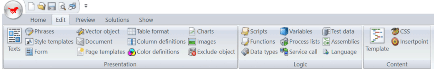
To manage or add charts that are going to be included in the documents, you select Edit in the top menu and then Charts or use right mouse button click when working in a text. Be adviced that when using Charts in combination with WebEditor the chart will be an image with an auto generated alt-attribute to satisfy user accessibility.
Chart Dialog:
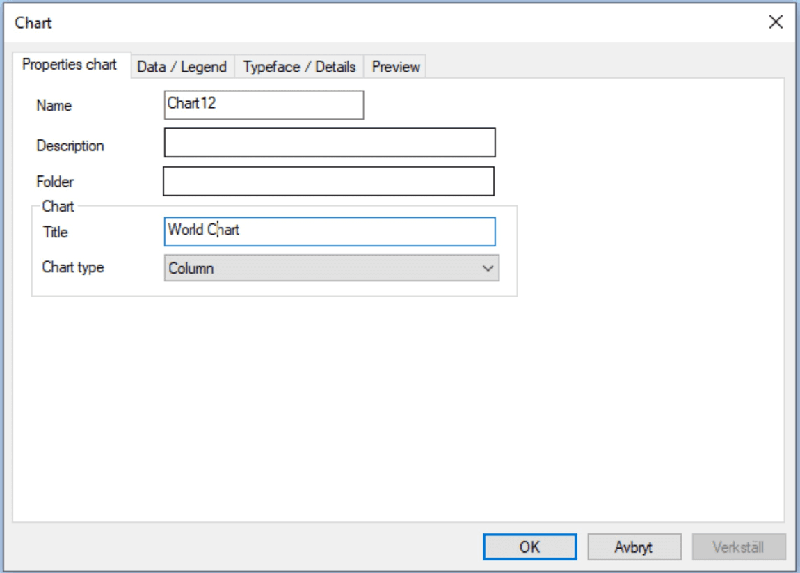
First you give the chart a name and description, then a foldername if you use folders.
| Function | Explanation |
|---|---|
| Name | The name of the chart. Can not be changed in Change Chart. |
| Description | A descriptive text of the chart item. |
| Folder | State search path in the tree of charts you have in the tool. |
In the Chart area you will define the header for and type of the chart
| Function | Explanation |
|---|---|
| Chart/Title | State title to be shown with the chart. |
| Chart/Chart type | State one of the following types: 3-D Column, 3-D Stacked column, Pie, Column, Stacked column or Area. For Example see tab Preview below. |
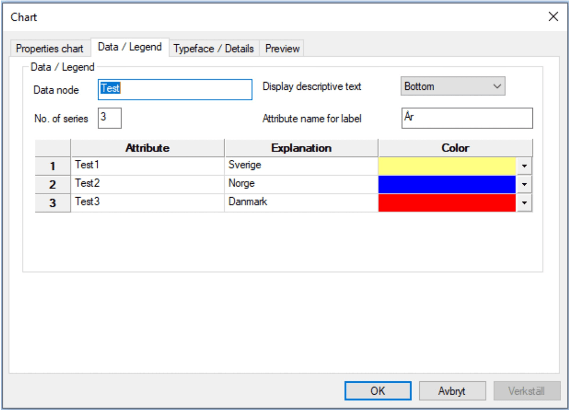
| Function | Explanation |
|---|---|
| Data node | State search path for the data node in the tree. |
| Show explanation text | State where to put the label. Bottom, Right or With value. |
| Number of series | State how many series to be included in the business chart. |
| Attribute name for label | State attribute name for the label. |
| Attribute | State attribute to be used for values. |
| Explanation | State explanation text for the attribute. |
| Color | State color for the attribute. |

| Function | Explanation |
|---|---|
| Headers/X-value | State label for the X-value. |
| Headers/Y-value | State label for the Y-value. |
| Typeface | State type face for the chart. |
| Details/Size in mm X | State width of the chart. |
| Details/Size in mm Y | State height of the chart. |
| Details/space between in % | State space between the bars in % of total width. |
| Details/3D-depth in % | State 3-D depth in % of total width. |
| Details/Background color | State background color. |
| Details/Show grid | State if help lines are to be shown. |
| Details/Suppress headers | State if labels are to be printed out or not. |
Content (HTML) (needs a license key)
Content is the latest added functionality to MetaTools basic features. Broadly speaking, Content is responsible for producing HTML based on document logic created in MetaTool and HTML templates with associated CSS3 style sheet created in their own development environment (right now) outside of MetaTool. For Content to work (= produce HTML), it needs MetaTool’s document logic content (letters, texts, images, etc.), Insertponts, Transformers, HTML templates and CSS files.

Why use Content/HTML? Benefits You Get!
We find useful:
- in MetaTool we can create pure self-supporting html - content template
- created html - content template can be sent with an e-mail message
- a template can be sent to Kivra and other electronic mailboxes to fulfill Kivra’s requirement that they can receive only self-supporting html format
- a template can be archived because in addition to tiff and pdf format we can archive self-supporting html format as well
- an html - content template can be integrated with the company’s existing webbsolution (My pages)
Content/HTML buildings blocks
Content menu group can be found under MetaTools Edit menu selection. It consists of 3 icons: template, css and insertpoint. We want to add to be able to produce Content / HTML in addition to these 3 elements we will need another “Transformers” element that does not have an icon in the Content menu group.
The main building blocks of Content are Templates, CSS, Insertpoints and Transformers.
Templates
Templates are one of the Content functionality main building blocks. They are built as an HTML structure. The basic task of the templates is to keep and show the selected content.
We start with creating our Content html template by clicking on the plus icon and open the Template window.
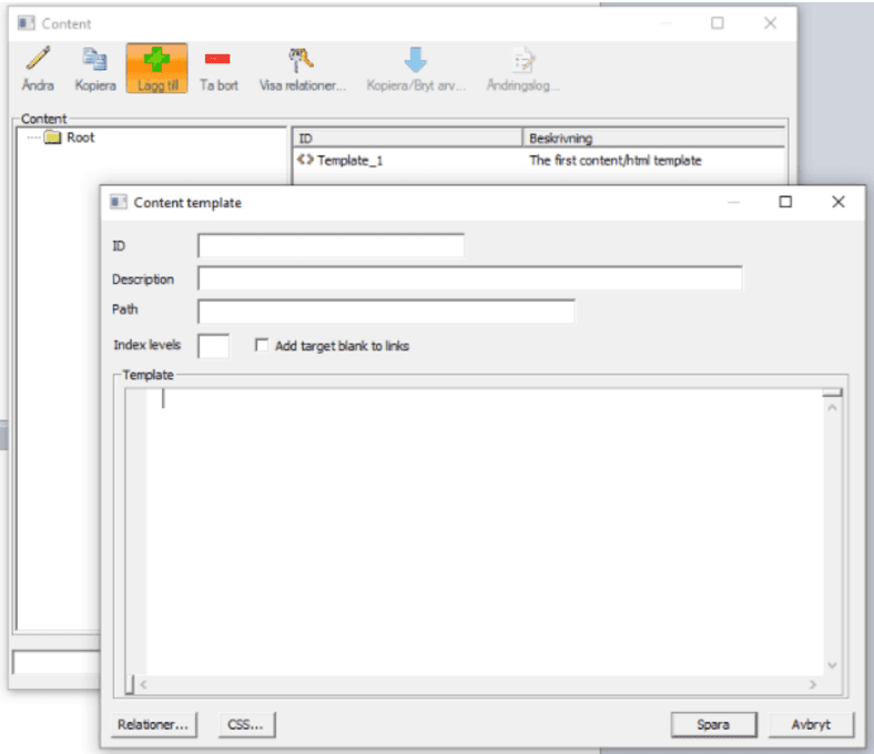
Here we choose suitable name and write a short description of our template. Then we can choose a name for the folder where we want to save our templates.
Now we have an empty Content / HTML template. To be able to save it, we need to build a basic html structure here within MetaTool.
<?xml version="1.0" encoding="UTF-8"?>
<!DOCTYPE html>
<html lang="en">
<head>
<meta charset="UTF-8"/>
<title>Test</title>
<metaforce-css></metaforce-css>
</head>
<body>
</body>
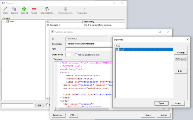
</html>Now we have our Content/HTML template with pure html code here. But MetaTool engine handles our Content template as pure XML format. So we need to add an introductory code that says it’s an XML format. Then we need to add some Metatool’s own tags to the document’s Head which takes care of the title, script and css references. Soon we will be ready, but we need to create a Content css(see CSS chapter) file that styles our Content template.
The template we made is very simple. In reality the documents have a significantly complicated structure. So we can continue to build our html template with the associated CSS style sheet which stands for styling of the template outside of MetaTool. Important to point out that when you program an HTML template always start with a finished document template and try to build the same structure with HTML elements and then style them with CSS3 style sheet. We don’t use JavaScript. The goal is to get an html / css template that is similar to our finished MetaTool document / letter
When you are happy with the result, copy the entire part of the html code. Open our content / html template in MetaTool and replace the part with the part that you copied from the html template outside of MetaTool. Save changes and now we have a complete content / html template. Furthermore, we must link our Content template and Content css file and we do that in the Content template window by clicking on the CSS button. There we select the css file we want to use. You can select one or more css files.
CSS
Content css file styles our Content template.
We create an new CSS by opening the CSS window and in the same way we did when we created the Content template, choose the appropriate name, short description and folder / path where we save and save created file.
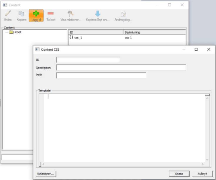
The next step is to go to the css file that we built in connection with the programming of html template outside MetaTool. Here we copy the entire contents of the css file. Open the CSS file into MetaTool and paste the content you copied before. Save and now we have our CSS file that styles our HTML template.
To keep in mind when using your own css classes and inline styling. This applies:
- inline style
 <div class="center"> <h1 style="color:orange;"><metaforce-insert
name="Header"></metaforce-insert></h1></div>- own CSS classes
 <div class="center"> <h1 class="test_heading"><metaforce-insert
name="Header"></metaforce-insert></h1></div>- Content CSS class
Transformers
Transformers is an element that allows us to transform / build an element in our Content template based on the information it receives from the HTML element to be bound with the selected content and information from CSS3 that styles the HTML element.
Nowdays we can transform headers, paragraphs, images, tables and accordions.
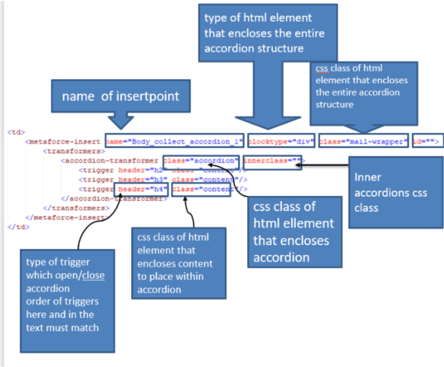
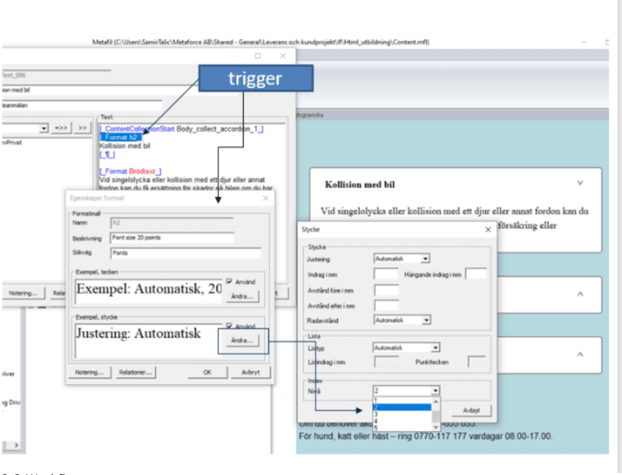
In the image above you can see the components of an accordion transformers with described associated attributes.
When we talk about triggers, it must be mentioned that the ordering of our headings within triggers is important and must match how we specified it in accordion transformers with which heading we chosen in the text should be our trigger. See image below.
Workflow
Here are all the steps needed in a process that builds Content / HTML.
- start by creating/reusing a document template with MetaTool
- create a new Content/ HTML template (with MetaTool)
- create Content/HTML CSS (with MetaTool)
- create a new HTML template (outside of MetaTool)
- create a new CSS3 style sheet (outside of MetaTool)
- create Insertpoints in HTML template as needed
- collect content to be displayed by inserting ContentCollectionStart/ContentCollectionEnd as needed within the document structure
- distribute Insertpoints within Content/HTML template
- preview HTML
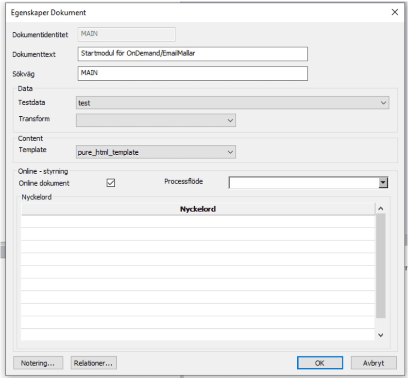
Suppose we have created a MetaTool document / letter, a Template, CSS and all Insertpoints we need. Before we start collecting our resources, we need to link our document template with our Content template. We do this with a right click on the document/letter and choose change. There we can choose which Content template we want to use.
Now is the time to start collecting resources we want to display in the Content template. You start from the top and work your way down to the end of the document. So we can collect for example our logo, heading, brief information, texts and images in the body of the text, heading number 2, accordions, footer. Open the document-template you want to work with. Place the CollectionStart tag where you want to start the collection and end the collection with the CollectionEnd tag. Now we have selected text that we want to display in the Content template.
Switch to our Content html template and choose html element for which we want to bind our content. Replace chosen html element with
<metaforce-insert name="Insertpointsname"></metaforce-insert>Similarly, we distribute all other Insertpoints in Content templates.
After we have collected all the resources to be displayed and shared them over our Content template, we can preview our Content template.